Installing Centos 7 Step by Step

The following is the steps I used to install CentOS 7 on my Lenovo laptop.

(This will be updated constantly)

Reference Guide– https://access.redhat.com/documentation/en-us/red_hat_enterprise_linux/7/

 
— Install the mini install 
 
— Run the nmtui command to configure the network (remember to set Manual instead of Automatic)
 
—  PREVENTING THE COMPUTER FROM SUSPENDING WHEN CLOSING THE LID
When closing the lid of your laptop, your computer suspends in order to save power. You can prevent the computer from suspending when closing the lid by changing the setting for that behavior.

Warning: Some laptops can overheat if they are left running with the lid closed, especially if they are in a confined place like a backpack. Therefore, consider if changing the default setting (suspend) is the best option in your case.

Open the /etc/systemd/logind.conf file for editing.
Find the HandleLidSwitch=suspend line in the file. If it is quoted out with the #character at the start, unquote it.
If the line is not present in the file, add it.
Replace the default suspend parameter with
lock for the screen to lock;
ignore for nothing to happen;
poweroff for the computer to switch off.
For example:

[Login] HandleLidSwitch=

HandleLidSwitch=lock

Save your changes and close the editor.
Run the following command so that your changes preserve the next restart of the system:
# systemctl restart systemd-logind.service


Warning: Keep in mind that restarting the service forcibly interrupts any currently running GNOME session of any desktop user who is logged in. This can result in users losing unsaved data.


For more information on the /etc/systemd/logind.conf file, see the logind.conf(5) man page.


— Add the most popular YUM repositories (refer to another Note)
 
— Install ifconfig command
# yum install net-tools
 
— Upgrade Kernel on CentOS 7 (refer to another Note)
 
— Install updatedb command
# yum -y install locate
 
— Install Denyhosts
# rpm -Uvh xxxx.rpm
start denyhosts service
config denyhosts configuration under /etc/denyhosts
 
— 

CentOS 6.6 plus Clonezilla & DRBL

A couple of years ago I set up an Ubuntu 10.0.4 with DRBL to clone Windows machines. Lately I was trying to do the same with the latest version of Ubuntu and it’s not successful. So I switched to CentOS 6 which I found out it’s pretty easy. Below is what I did.

The Clonezilla/DRBL server is a Dell old laptop with one NIC with a 160GB hard drive.

1. Install CentOS 6.6 minium. Make sure you assign a static private IP address to the NIC.

2. Turn off iptables and selinux.

#service iptables stop

#chkconfig iptables off

#vi /etc/sysconfig/selinux

change SELINUX from “permissive” to “disabled”

reboot your machine

3. Install DRBL key

#rm -f GPG-KEY-DRBL

#yum install wget

#wget http://drbl.org/GPG-KEY-DRBL

#rpm –import GPG-KEY-DRBL

4. Download the DRBL rpm package. You can visit http://drbl.org/ to download

5. CD to the downloaded file path, run

#yum install xxxxx.rpm

That way it will install all the dependencies.

6. Now run

#drblsrv -i

example: http://drbl.org/installation/examples/drblsrv_desktop_example.txt

7. Add eth0:1 virtual NIC

Please edit the file:
/etc/sysconfig/network-scripts/ifcfg-eth0:1
like this:
-----------------------------------------------
DEVICE=eth0:1
BOOTPROTO=static
BROADCAST=192.168.100.255
IPADDR=192.168.100.254
NETMASK=255.255.255.0
NETWORK=192.168.100.0
ONBOOT=yes
-----------------------------------------------
then run "/etc/init.d/network restart" to restart the network.

8. Reboot the machine

9. Now run

#drblpush -i

For this, make sure it sees TWO NICs, eth0 and eth0:1. The DRBL/Clonezilla server will act as the DHCP server. The client machines will get the IP addresses from the only NIC interface.

10. After setting up, you should disconnect the Ethernet cable from the router before you start the DRBL service. If you still have the Ethernet cable connected to the router there will be DHCP servers conflict.

11.

Start Clonezilla Server

Run:

# /usr/drbl/dcs

First screen Choose “Select all the clients“.

Second Screen Choose “clonezilla-start“.

Third screen choose  “Beginner mode”. 

Fourth screen choose “select-in-client“. This gives you to option to choose whether to restore or save the image during Clonezilla’s booting process in the client itself.

The rest screens, click “ok” and we are done!

12. You can now connect your laptop and your client machines to the same LAN; Boot your client machines using the PXE boot.

About Apple Bonjour – Great Article

First of all: The following is not my writing. I copied it here just for future reference. If there is copy right issue, please contact me and I will remove it right away. 

I copied it from this link: http://blogs.brandeis.edu/netsys/2012/02/07/bonjour-hello-apples-misunderstood-zero-conf-protocol/

Thanks very much for the author to write up this great article.

———————————————————–

FEBRUARY 7, 2012POSTED IN: NETWORK

If you have ever used an Apple product in the last 8 years you have participated in Apple’s Bonjour network. Apple, being Apple, wanted to magically connect their devices. They didn’t want users entering ugly IP addresses or having to set up a directory of devices, that would be messy! They didn’t even want us propeller heads to be able to mess things up so they hid this magic behind a name. Originally it was called Rendezvous but someone owned that and probably wanted too much money for Apple to use it. (Actually this was probably a better name as it means a place to meet up) so they stuck with the French and renamed it Bonjour (hello in French).

So what IS Bonjour? Well, it is really two protocols, mDNS or multicast domain name system and DNS-SD or Domain Name System Service Discovery. Apple uses these two standard protocols to discover and advertise their services, like AppleTV or iTunes libraries, SSH, SAMBA, wireless routers etc. What is discovering a service? Well, in real terms, if you turn on your Apple product you may want to connect to some service over the network – say a file share or an Airplay device like a remote speaker or display. But how do you find these devices if you don’t know where they are on the network? Simple, you shout over the network and ask for them! OK, that is oversimplifying the issue, but it’s not far off from what really happens.

When your Apple product gets on a network it starts up the multicast DNS process (mdnsresponder) and sends a multicast join request to the address 224.0.0.251. What is multicast? Well that’s a longer post, but think of it as shouting with style. Your device then sends out a register or a hello announcing its intention to have a name on this network. It uses the name given by you, like John’s iPhone. Because all of these devices need a domain and this is all local, it uses the domain .local as in “John’s iPhone.local”, escaping all the illegal characters so they display all pretty to the user. The other devices do this greeting as well.

Each device participating in the mDNS group maintains a DNS server and a DNS cache. It serves out only its own services and computer name to IP mapping and caches the results of the queries it makes. Bonjour can also use a real DNS server to register itself and the services it has to offer but your DNS system must be set up for dynamic DNS and service discovery. It does this by attempting to register itself with the domain presented to it by the DHCP server.

OK, so now you are on your network and have an IP address but now you want to print or share something local. When you open your add printer wizard your device sends a new request to its fellow mDNS neighbors. It says, “Hey are there any printers on this network?” If there are printers shared on the network they respond and send their names to your computer. Once you attach to the printer, your computer sends print commands like it would had you known the IP address. However, since you discovered it by name, you save the name and not the IP address. In technical details, this means that your device made a DNS service discovery request.

Apple has some good documents on this here but here is a pretty picture that shows this happening:

All of this happens very nicely on your home network where there is only one network with one subnet. However, in an enterprise like Brandeis, it gets way more complicated. In order for Brandeis to support large numbers of users we need to set up lots of networks with lots of subnets.  Because users move around with their devices, and there are a lot of mobile devices at Brandeis, we use a technology called VLAN pooling. This provides lots of room for users. The down side is that a user’s device and the device they want to connect to will most likely will not be in the same subnet.

This is a pain. Unfortunately, there is not much we can do now to “fix” this. However, we are working on a fix with our wireless vendor that will address this issue in a very cool way! More to come on this!

UPDATE: I forgot to add this in: bonjour supports registering with enterprise DNS. This is also called wide area bonjour

Here are some links about this:

Convert a Cisco AIR-LAP1142N-A-K9 to Autonomous AP

Our school has quite a few 1142N-A-K9 APs that used to connected to and controlled by the Cisco 4402 Controller. Now we upgraded the school wifi system using a newer version of controller (5508) and replacing the old APs with newer model 3702. So I have been thinking of converting an old 1142N AP to a standalone one just for fun. There are a lot articles from Google giving instructions and I have been struggling following those instructions. Eventually I made it work. The main obstacle I experienced is when the AP was trying to load the standalone firmware from the TFTP server it did not work. So below I will write down the steps that work for me.

What you need:

Cisco 1142N-A-K9 AP (with power adapter or using the power injector);
Laptop;
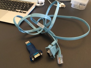
Cisco serial console cable and USB-to-Serial adapter;

IMG_2374
A switch and two Cat5 cables (one to the AP and one to the laptop);

Steps to follow:
1. Install TftpServer on my Macbook Air;
2. Download the standalone version of the image software (c1140-k9w7-tar.124-25d.JA.tar) Here; (If the download link does not work, please Google search c1140-k9w7-tar.124-25d.JA.tar)
3. Configure the TFTP server in the laptop;
4. Configure your laptop’s Ethernet connection ( I was using an USB-to-Ethernet adapter) to use static IP 10.0.0.2 with netmask 255.0.0.0, NO Default Gateway/Router;
5. Connect your laptop Ethernet cable to the switch and connect the other cable from your AP (Ethernet port) to the switch. Power on the switch;
6. Connect your AP’s Ethernet port to the switch;

— With the above a few steps your TFTP server is ready to serve the image software

Next:
7. Connect your Cisco serial console cable to the USB-to-Serial adapter, then connect the adapter to your Mac. Connect the Cisco serial console cable to the Console port of the AP;
— I don’t want to go through on how to make your USB-to-Serial adapter work with the Mac. Google can help you.
8. Open your Terminal program (or use Zterm app) and run the “screen” command to start capturing;
9. Hold down your “Mode” button of the AP while plugging in the power of the AP;
10. You can see now see the Terminal is displaying the AP startup messages. Keep holding the Mode button until you see the AP showing the red light, then release the Mode button.
11. On the Terminal window, you will see it’s trying to load the software image from the TFTP server without success and finally give you this “ap:” on the screen.

Next, run the following commands:

ap: delete flash:private-config
ap: delete flash:private-multiple-fs
ap: set IP_ADDR 10.0.0.1
ap: set NETMASK 255.0.0.0
ap: set DEFAULT_ROUTER 10.0.0.2
ap: tftp_init
ap: ether_init
ap: flash_init
ap: tar -xtract tftp://10.0.0.2/c1140-k9w7-tar.124-25d.JA.tar flash:
ap: set BOOT flash:/c1140-k9w7-mx.124-25d.JA/c1140-k9w7-mx.124-25d.JA
ap: set
BOOT=flash:/c1140-k9w7-mx.124-25d.JA/c1140-k9w7-mx.124-25d.JA
DEFAULT_ROUTER=10.0.0.2
ENABLE_BREAK=yes
IP_ADDR=10.0.0.1
MANUAL_BOOT=no
NETMASK=255.0.0.0
NEW_IMAGE=yes
PWR_INJECTOR_DETECT=000b.fd04.0982
RELOAD_REASON=23
ROM_PERSISTENT_UTC=1014941743
TERMLINES=0
ap: boot

After it boots, you will get the “ap>” prompt. Run the following commands:

ap>en
Password: Cisco (this is case sensitive)
ap# config t
ap(config)# interface GigabitEthernet 0
ap(config)# ip addr 10.0.0.1 255.0.0.0 (or whatever IP you need on your production network)
ap(config)# interface BVI1
ap(config)# ip addr 10.0.0.3 255.0.0.0 (same network as the Ethernet interface)
press ctrl+z to exit config
type wr to write the config

Next:
Open your browser from the laptop and access the AP’s web GUI from http://10.0.0.1. Usename and password are both Cisco.

— With the above steps you successfully loaded the standalone image to the AP.

Next, we will see how to configure your AP so that it can serve the wifi clients.

From the Terminal, telnet to 10.0.0.1, then run the following commands:

Username: Cisco
Password:
AP1142>en
Password:

AP1142#conf t
Enter configuration commands, one per line. End with CNTL/Z.
AP1142(config)#interface dot11Radio 0
AP1142(config-if)#no shutdown
AP1142(config-if)#do sho ip inter b
Interface                            IP-Address                      OK?                Method                Status                             Protocol
BVI1                                  10.0.0.3                            YES                manual                 up                                   up
Dot11Radio0                     unassigned                      YES                unset                    administratively down    down
Dot11Radio1                     unassigned                      YES                unset                    reset                               down
Dot11Radio1.1                  unassigned                      YES                unset                    reset                               down
GigabitEthernet0               10.0.0.1                            YES                manual                 up                                   up
GigabitEthernet0.1            unassigned                       YES                unset                    up                                   up

AP1142(config-if)#encryption vlan 1 mode ciphers tkip aes-ccm
AP1142(config-if)#channel 1
AP1142(config-if)#antenna gain 128
AP1142(config-if)#station-role root
AP1142(config-if)#ssid 1142wifi
AP1142(config-if-ssid)#vlan 1
AP1142(config-if-ssid)#authentication key-management wpa version 2
AP1142(config-if-ssid)#guest-mode
AP1142(config-if-ssid)#wpa-psk ascii C!sC0

How to set up an OpenVPN server on a Tomato router?

This is what I was trying to do: I have a Netgear WNR3500L V2 wifi router loaded with the TomatoUSB firmware 1.28. I want to enable the OpenVPN feature so that I can VPN to my home network while I am at work.

I tried Google search to find out the best answer to set it up and I ended up THIS one.Thanks very much for the author who wrote the excellent instructions. I did it on my Macbook Air (running Mavericks) through the Terminal app. There are two things I want to point out when I was following the instructions:
1. When I ran the command
git clone git@github.com:OpenVPN/easy-rsa.git

It did not work. It says the following:
Permission denied (publickey).
fatal: Could not read from remote repository.
Please make sure you have the correct access rights
and the repository exists.

So I have to visit the site (https://github.com/OpenVPN/easy-rsa), and download it by Clone in Desktop or Download ZIP from the right side of the web page.

2. In the last step about Generating Client Certificate and Key, after I ran the commands, I don’t know where is the certificate file (the client.crt) located because it did not tell. It only tells where the ca.key is. The answer is it’s located under the /home/user/openvpn/easy-rsa/easyrsa3/pki/issued/ directory.

SSH Public and Private keys

As a SSH client, when you run command, ssh-keygen -t rsa, under your user’s .ssh directory, you generate a key pair (bolded),like below:

l-fung-2:.ssh fung$ ssh-keygen -t rsa
Generating public/private rsa key pair.
Enter file in which to save the key (/Users/fung/.ssh/id_rsa):
Enter passphrase (empty for no passphrase):
Enter same passphrase again:
Your identification has been saved in /Users/fung/.ssh/id_rsa.
Your public key has been saved in /Users/fung/.ssh/id_rsa.pub.
The key fingerprint is:
3d:30:b0:79:be:3e:80:42:09:0b:51:33:42:74:8d:f0 fung@L-Fung-2.local
The key’s randomart image is:
+–[ RSA 2048]—-+
|=*=.o .          |
|o.o+ . +         |
|.o E  o +        |
|. o    o +       |
| .   .  S o      |
|  . . .  . .     |
|   .   ..        |
|       ..        |
|        ..       |
+—————–+

The id_rsa.pub is a public key needs to be uploaded to the server you want to access. The id_rsa is a private key (confidential and don’t lose it) used to verify with the id_rsa.pub key. On the server side, you will need to add the id_rsa.pub key to the file called known_hosts.